
Recently added item(s)
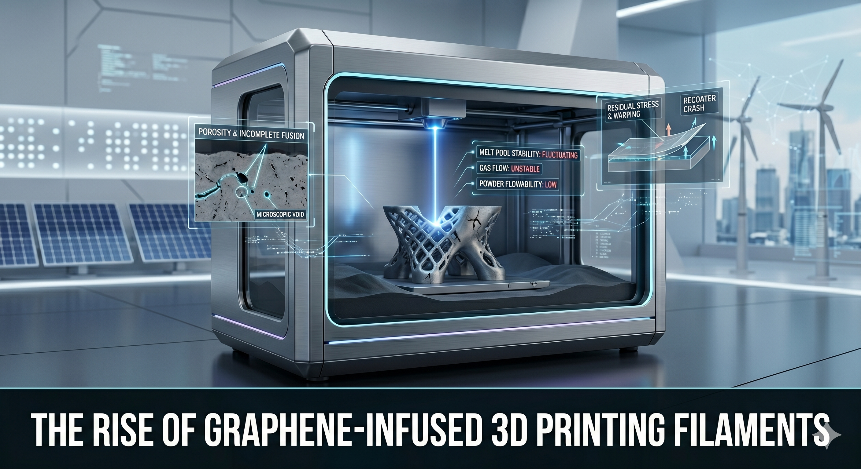
Metal Powder Bed Fusion (PBF), particularly the laser-based variant (L-PBF or DMLS/SLM), is often hailed as the gold standard for industrial metal 3D printing. By using a high-powered laser to selectively melt fine metal powders layer by layer, it enables the creation of highly complex geometries that are impossible to achieve via traditional machining or casting. However, this transformative technology is not a “plug-and-play” process. It is a highly sensitive engineering endeavor that occurs within a harsh, closed environment where thousands of variables must align perfectly.
When a print fails or when parts exhibit hidden defects, the consequences are expensive—involving wasted material (titanium, nickel superalloys, or specialized steels), machine time, and engineer resources. More critically, for high-stakes industries like aerospace and medical implants, a flawed part can compromise structural integrity or biocompatibility.
This article provides a detailed engineering guide to troubleshooting the most common issues encountered in Metal PBF, translated into accessible language, integrating current industrial best practices and material performance studies.
The Root Causes: Powder and Processing Parameters
Before diving into specific defects, it is crucial to understand that PBF troubleshooting always circles back to two primary pillars:
-
Powder Quality (The Input): Moisture, contamination, poor flowability, or improper particle size distribution (PSD).
-
Processing Parameters (The “Recipe”): Laser power, scan speed, hatch spacing (the distance between laser paths), and layer thickness.
These elements must be tuned for specific alloys (like Titanium-6Aluminum-4Vanadium) and even specific machine environments. When they diverge, the following issues occur.
1. Porosity and Incomplete Fusion: The Unseen Weakness
Porosity refers to microscopic voids or holes trapped within the solid metal part. It is perhaps the most insidious issue in metal AM because the part may look perfect on the outside, but it lacks dynamic strength, making it prone to premature fatigue failure.
Keyhole Porosity vs. Lack of Fusion (LOF)
We must distinguish between two different types of porosity by analyzing their shape and cause through cross-sectional microscopy.
-
Keyhole Porosity (Over-melting): These are generally spherical voids found deep at the base of the melt pool. This happens when the laser energy density is too high (either too much power or too slow speed). The laser essentially “drills” into the material, vaporizing metal and creating a deep cavity. When this cavity collapses before metal flows back in, gas gets trapped, creating a small bubble.
-
Lack of Fusion Porosity (LOF – Under-melting): These are irregular, often “crack-like” voids, frequently containing un-melted powder particles. They usually occur between layers or between adjacent scan lines. LOF happens when the energy density is too low (not enough power or too fast speed) to fully melt the current powder layer and re-melt the layer beneath it. Without this “inter-layer welding,” the structure is weak.
Troubleshooting and Fixes
-
Optical Melt Pool Monitoring: Modern industrial machines (from EOS, Renishaw, or GE) now utilize photodiodes or high-speed cameras to monitor the light and heat emitted from the melt pool in real-time. This in-situ monitoring can flag deviations from the norm, allowing operators to stop a doomed print early.
-
Parameter Window Refinement: Engineers must perform extensive test prints (density cubes) to map the “process window” of a specific alloy, finding the sweet spot between Keyhole and LOF regimes.
-
Powder Moisture Control: Spherical voids can also be caused by moisture on the powder. Damp powder releases hydrogen gas during melting. Powder must be stored in specialized cabinets with low humidity and vacuum-sealed containers.
2. Residual Stress, Warping, and Recoater Crash: The War of Temperatures
The defining feature of PBF is rapid solidification. We are melting metal at ~1600°C and it is cooling to ~200°C within fractions of a second. This extreme temperature gradient creates intense internal force, known as residual stress.
Think of it this way: hot metal expands, but it is welded to a colder layer beneath it. When the hot top layer tries to shrink upon cooling, the layer beneath it prevents it from contracting. The top layer remains “stretched” (in tension), while the bottom layer is squeezed (in compression).
The Visible Symptoms: Warping and Cracking
If these stresses exceed the material’s strength, one of two things happens:
-
The Part Warps: The tensile stress pulls the part away from the build plate. It curves upward (the “potato chip” effect).
-
The Part Cracks: The material itself tears apart, often at delicate intersections or edges.
-
The Recoater Crash: This is the nightmare scenario. If a part warps upward, it may rise into the path of the recoater (the mechanism that spreads the next layer of powder). The recoater smashes into the hardened part, often damaging the recoater blade, shifting the entire build plate, and instantly failing the print.
Troubleshooting and Fixes
-
Heated Build Plates: Pre-heating the build plate (to 200°C+ for Ti-6Al-4V) reduces the initial temperature difference between the melt pool and the substrate, thereby lowering residual stress.
-
Strategic Support Design: Support structures do not just hold a part up; they act as critical heat sinks, drawing heat away from the part to the build plate. Optimized support geometry is essential for delicate or large, flat areas.
-
Build Orientation: Tilting a large, flat part relative to the build plate (e.g., to 45 degrees) minimizes the area of any single layer, reducing the global tensile stress.
-
In-Situ Recoater Monitoring: New technologies use cameras and sensors to detect any part protrusion before the recoater moves, stopping the machine to prevent mechanical damage.
3. Poor Surface Roughness and “Balling”: When Metal Bead Up
Surface roughness is an inherent feature of PBF because some powder particles always semi-fuse to the exterior walls of the part. However, extreme surface issues can degrade aesthetics and functionality.
The Phenomenon of Balling
If surface roughness appears as a series of bead-like bumps, it is called balling. This happens when the laser moves too fast for the material’s surface tension and viscosity. The melt pool “breaks up” into discrete droplets instead of forming a continuous, smooth bead. This is similar to how water beads up on a waxed car surface rather than spreading smoothly.
Troubleshooting and Fixes
-
Reduce Scan Speed: Slowing the laser slightly allows the melt pool to stabilize and wet the substrate more effectively.
-
Optimize Gas Flow: The process chamber must be purged with inert gas (Argon or Nitrogen) to prevent oxidation. Crucially, the uniformity of this gas flow across the powder bed must be consistent. Turbulence or low flow zones can lead to poor powder fusion and excessive roughness.
-
Powder Sphericity: Angular or oddly shaped powder particles do not flow well and can cause uneven layer density, leading to localized balling and fusion issues. Always use certified, spherical AM powders.
4. Advantage–Risk Assessment in Metal PBF Troubleshooting
For industrial application managers, the entire process must be viewed through a risk assessment lens.
The Advantages (Why We Trouble)
-
Geometric Freedom: Achieving geometries for things like conformal cooling channels (curving cooling holes that follow the contour of a part) is only possible through AM and is essential for optimizing heat transfer in rocket engines or plastic injection molds.
-
Performance: Corrected and optimized PBF parts (specifically Ti-6Al-4V) can achieve static and fatigue material properties that match or exceed traditional forgings, provided porosity and stress are controlled. This is supported by multiple fatigue life studies performed on medical grade AM implants.
-
Personalization: The ability to trouble and produce personalized, patient-specific orthopedic implants (e.g., customized hip stems) based on CT scan data is a major benefit in the “clinical studies” context of bio-AM, provided the material density and surface are certified safe.
The Risks and Challenges
-
Cost of Certification: The most significant risk is not just a failed print, but a “failed” certification. To use PBF for aerospace or medical components, every single batch must go through rigorous CT scanning (to detect porosity) and tensile testing. This makes troubleshooting a mandatory, non-negotiable cost.
-
Material Volatility: Working with reactive metals like titanium or aluminum powders carries inherent safety risks, including dust explosion hazards, requiring specialized safety equipment and facility engineering.
-
The “Black Box” Problem: Every AM machine has slightly different internal environmental dynamics. A perfect parameter set from Machine A may fail on Machine B, making the standardization of troubleshooting procedures incredibly difficult.
Conclusion: The Path Forward – AI and In-Situ Solutions
Troubleshooting common issues in Metal Powder Bed Fusion is not a matter of guessing; it is a discipline that combines material science, optical monitoring, and rigorous parameter optimization. We are moving away from an era where we rely solely on destructive testing after the build (where we waste a part just to see if it was good).
The future of PBF reliability lies in In-Situ, Closed-Loop Control. Current research is integrating photodiodes, acoustic sensors, and AI/Machine Learning algorithms that analyze sensor data in real-time. These systems will not just detect keyhole porosity or delamination mid-print; they will have the intelligence to automatically adjust the laser power, scan speed, or recoater parameters on the fly, preventing defects before they fully form.
Until that automated future is standard, successful metal AM requires a methodical engineering culture that focuses on powder purity, heated build plates, strategic support, and a detailed parameter window assessment. Mastering these “melt pool dynamics” is what separates experimental prototypes from certified, high-performance components.